During experiments with Java version of Lego motor controller and built-in LeJOS motor controller I found that they use different approaches to implement smooth acceleration. Lego controller uses integer arithmetics and implements non-linear acceleration algorithm. It divides the acceleration distance to the speed delta and gets the interval to increase speed for 1 degree/sec. Each time when the motor covers the interval, the controller increases its speed for 1 degree/sec. This algorithms is simple but acceleration is non-linear. LeJOS uses different approach. The version I tested had problems with smooth acceleration. But LeJOS team has published an updated version of motor controller that works well. This version implements linear acceleration approach using floating point arithmetic. Also LeJOS controller uses much smalled discretization interval (interval between regulation cycles). Lego controller uses 100ms interval, LeJOS controller uses 4ms interval. This small regulation interval has some advantages and disadvantages: it provides more fast reaction to change of external load but requires more CPU time, especially being implemented in Java. Lego controller is implemented in native ARM code and works faster.
I wanted to make a controller that has best qualities of LeJOS controller but requires less CPU time. I tried to increase discretization interval but found that this controller has problems with rotation to a specified angle. It could not reach the target position with zero speed and requires additional time to reach the target point.
To implement smooth acceleration, I used motion profile generator that calculated the next position at each regulation cycle and PID regulator that should keep the specified position. This regulator works well when the set point changes slowly. But when we use smooth acceleration, the set point is changed each regulation cycle and the regulator has some constant delay in reaching the target position. As as result, the motor comes in the target rotation position with non-zero speed and spends some time for oscillations around the target point. This inaccuracy could be reduced by using smaller discretization periods, but I did not want to do that because I wanted to decrease CPU load.
Then I decided to extend my controller with feed-forward that should calculate the base power that need to ensure rotation to the specified angle. In this case PID regulator should only compensate the impact of the external load.
PID Controller With Motion Profile Generator
Because Lego controller is focused on speed regulation, it cannot provide good precision in case when we need to reach a particular position and keep it. To provide such ability in my motor controller I decided to use PID regulator that focused on position regulation. To provide speed regulation (especially with smooth acceleration) I implemented motion profile generator. It calculates the new position each regulation cycle. This approach allows me to implement different acceleration algorithms using different motion profile generators. I implemented two generators. Using them, the user can turn smooth acceleration on and off.
 |
| Example of generated motion profile with smooth acceleration |
 |
| Example of generated motion profile without smooth acceleration |
Using Feed-forward to Improve Response to Command Signals
To use feed forward we should implement the system with two degrees of freedom.
 |
| The system with two degrees of freedom |
Finding the inverse of the motor model
To find inverse of motor model we should find the motor model itself. I used following differential equations to describe mechanical and electrical state of DC motor:

where:
| i e | (A) (V) | armature current armature voltage |
| ω τd | (rad/sec) (N·m) | shaft's angular velocity shaft's load torque |
| La Ra Kτ Kb | (H) (Ω) (N·m/A) (V/(rad/s)) | armature inductance armature resistance torque constant back electromotive force coefficient |
| J B Ar | (kg·m²) (N·m/(rad/s)) (N·m) | rotor's moment of inertia viscosity resistance coefficient dry friction force |
As I described in my previous post, I calculated these constants from measurements of motor under load performed by Philo and used them to emulate the NXT motor:
Ra = 5.262773292
Kb = 0.4952900056
Kτ = 0.3233728703
B = 0.0006001689451
La = 0.0047
J = 0.001321184025
Ar = 0.007299397206
To find the inversion of the transfer function we should make some approximations. I assumed:
ω(0) = ω0, i(0) = f(ω0).
To calculate f(ω0) I supposed that the system is in steady state (ω=const. and i=const.) at the initial moment. In this case these differential equations are represented by the following linear equations.

From this system of equations we can find i(0):


We want to find the inverse function in form voltage(distance, ω0). To do this, we need to find integral of the angular velocity and then find the inverse function from it.

power = (7299431.476·distance+11879.49780·signum(velocity)-28316.23421·velocity) / Battery.getVoltageMilliVolt()
power = (152012.7242·distance+11879.49771·signum(velocity)-2918.826420·velocity) / Battery.getVoltageMilliVolt()
To check accuracy of this function we can disable PID regulator and test the motor using only feed-forward component.
 |
| Feed-forward only regulation on emulator. |
At the end of rotation the error is 1degree. This result has been got on emulator. We can expect that the controller will work without errors on emulator, but rounding the motor power value produces some non-linearity.
The following diagram shows the real motor measurement.
 |
| Feed-forward only regulation on Lego motor. |
Kb=0.5002900056
Ar=0.009599397206
New feed-forward functions for 4ms and 25ms discretization periods are:
power = (7300460.329·distance + 15622.66220·signum(velocity) - 28311.62297·velocity) / Battery.getVoltageMilliVolt()
power = (152250.9950·distance + 15622.66225·signum(velocity) - 2916.056542·velocity) / Battery.getVoltageMilliVolt()
In this case the result looks better:
 | |||
| Feed-forward only regulation on Lego motor. Rotation to 400 degrees. |
 |
| Feed-forward only regulation on Lego motor. Rotation to 4000 degrees. |
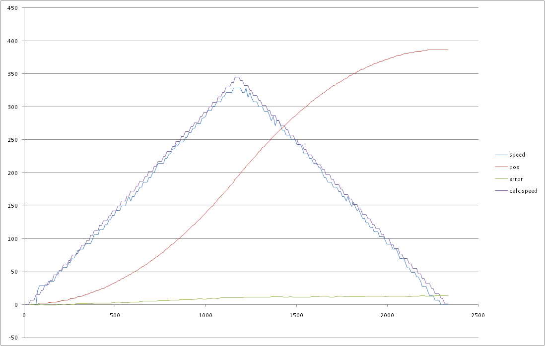
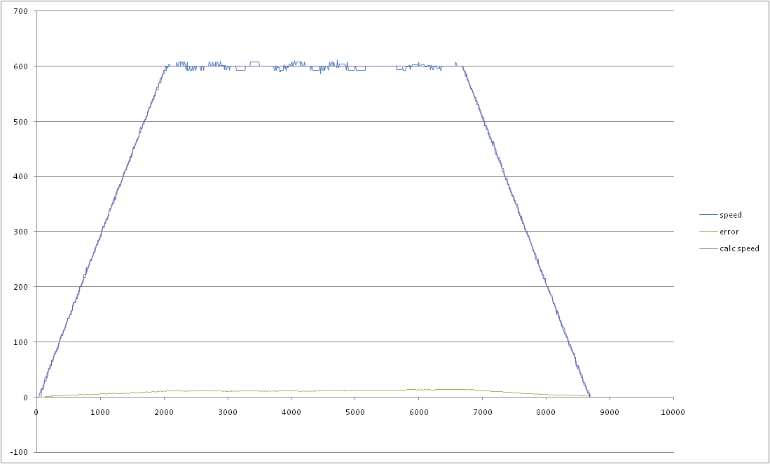
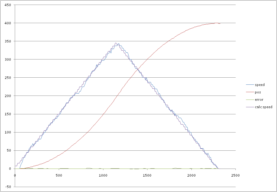
Then we will test the controller with closed feed-back loop. I used two scenarios - rotation to 400 and 4000 degrees. To estimate impact of feed-forward I will test the motor in two modes: feed-back only and feed-back with feed-forward. I used PI regulator in feed-back loop. The motor controller performs rotation to the specified angle and when this angle is reached and regulation error is less that 1 the controller switches to "stop" state where it keeps the current position. All following tests run until the motor switches to "stop" state.
 |
| Rotation to 400 degrees using only feed-back. Emulator. |
 |
| Rotation to 4000 degrees using only feed-back. Emulator. |
 |
| Rotation to 400 degrees using only feed-back. NXT motor. |
 |
| Rotation to 4000 degrees using only feed-back. NXT motor. |
 |
| Rotation to 400 degrees using feed-back and feed-forward. Emulator. |
 |
| Rotation to 4000 degrees using feed-back and feed-forward. Emulator. |
Then we will test the controller using the real motor.
 |
| Rotation to 400 degrees using feed-back and feed-forward. NXT motor. |
 |
| Rotation to 4000 degrees using feed-back and feed-forward. NXT motor. |
Feed-back regulator
As feed-back regulator I used PID regulator. I used algorithm described in [1]. I turned off derivative part and used the controller as PI controller, because derivative component produces high-frequency noise and makes rotation precision worse. But PI controller has some disadvantages.
Let's compare how LeJOS motor controller and my controller respond to change of load force. I will use the emulator to test scenario when the motor runs without load, but from 4 till 5 second some external load is applied to the motor's shaft.
 |
| Step response of my regulator |
 |
| Step response of LeJOS regulator |
CPU load
I used two tests to measure CPU load. In the first test I executed the regulation function in loop, on fake data, and measured average execution time. In the second test I tried to measure CPU load on working motor. This test increments an integer variable during 5 seconds. The first run is performed without running motors. Its results serves as a base. The second run is performed when one motor is running. Ration of these results gives me a percent of available CPU time.
Results of the first test:
My controller: 754 microseconds.
LeJOS controller: 595 microseconds.
Execution time of my controller is bigger because it uses multiple classes to implement its parts: motion profile generator, feed-forward calculator and PID regulator. When I combined all of them in a single class, I found that this variant of controller requires 597 microseconds to run.
The second test results (numbers of iterations):
My controlller: base: 374955, motor is running: 366222. CPU load 2.33%
LeJOS controller: base 374993, motor is running: 319285. CPU load 15%
These results are for one motor. When other motors are running we should multiple these values to number of working motors.
Conclusion
I wanted to make a motor controller that would provide the same interface as LeJOS motor but would consume less CPU time. I found that using long discretization periods together with feed-forward allow me to make such controller.
Another reason for starting of this project was the fact that LeJOS motor had not worked well with low acceleration values. However, the current version of LeJOS controller works well, but requires much CPU time.
By the way, I found another way to reduce CPU load in the motor controller. I converted my controller to C++, compiled it into native ARM code and tested it under nxtOSEK. In this case it requires only 61 microseconds to one regulation cycle. I think it is a interesting point to my next project.
Bibliography
[1] Åström, K. J. and T. Hägglund. Advanced PID control. - ISA - The Instrumentation, System, and
Automation Society, 2006
12 comments:
Hi Maxim,
Nice blog you have here. I came across Philippe Hurbain's excellent website sometime ago. On the Motor Internals page, there is a link that points to Ryo Watanabe's page containing information on NXT motor parameters. On that page, the torque constant (Kt) and back-EMF constant (Kb) have rather different values. In theory, they are supposed to be numerically identical when using SI units. Naturally, some level of empirical error is expected when data is obtained experimentally. However, the discrepancy between the two values is large enough for one to question the validity of the data used for deriving the motor constants. I noticed a similar discrepancy in your calculated values as well, although yours are numerically different from Prof Watanabe's.
http://www.philohome.com/nxtmotor/nxtmotor.htm
http://web.mac.com/ryo_watanabe/iWeb/Ryo%27s%20Holiday/NXT%20Motor.html
I've emailed Prof Watanabe a couple of times already without getting a reply. Do you have any idea why there is such a significant discrepancy between Kt and Kb? Thanks.
Cheers
Hippie
I used measurements results from this page http://www.philohome.com/motors/motorcomp.htm. In that case Philo used a laboratory power supply instead of batteries. The power supply has very small inner resistance. But in this case (http://www.philohome.com/nxtmotor/nxtmotor.htm) he used batteries and accumulators that have significant inner resistance. It can explain the difference in constants.
Thanks for the explanation on why your values and those of Prof Watanabe (using Philo's battery-powered results) are different. However, I still don't understand why the discrepancy between Kt and Kb is so large. Both Watanabe's and your calculations show that Kb is about 50% larger than Kt. Could it be caused by some unaccounted factor? If it's only due to experimental error, this sort of margin usually leads to questions about the accuracy of the original data.
I have not tested the load characteristic of the NXT motor. I have only Philo results. There is another source of NXT constants (http://www.zcuba.dk/reports/06gr508.pdf), but it does not contain the load tests. If we assume that Kt equals to Kb we will get stall torque 90 N*cm. But from Philo's tests we know that stall torque is 50 N*cm. Probably, it is necessary to do another test to verify Philo results.
Thanks for the link to that report. There is some variance between the raw data in the report and those of Philo's, but that is to be expected for any empirical data. So, it's not surprising that there's some difference among the parameter values derived by you, Watanabe and the authors of the report.
I did notice that the authors assumed both Kt and Kb to be equal and only calculated the latter. In my opinion, they should have calculated Kt as well, and then compared the two.
At the moment, I'm trying to conduct simulations of the NXT motors, so having the most accurate data is of utmost importance. Unfortunately, my electrical engineering knowledge is quite limited as my training is in mechanical engineering. In your opinion, would it be more realistic to use the values derived by data obtained using battery power instead of mains power?
Cheers.
I think if you need to perform a precise simulation, you need to include inner battery resistance into the model based on the mains power, because the battery voltage will depend on the motor load.
I did not do so. My regulator calculates the feed-forward using the current battery voltage.
Really, it provides a more rapid response, the external load changes, but requires more CPU time, especially in Java to achieve. LEGO controller for ARM code and works in the local faster.
Motor controller
Hey ,
I am a student at university and for my project, I do need to estimate this lego's dc motor's parameters, I have seen that you have calculated all parameters, in fact when I showed my professor the data of http://www.philohome.com/motors/motorcomp.htm, he told me that I can not use them since I need the precise modeling of DC motor. Could you please let me know if it is possible to have an open loop ( without controller effect on motor) test on motor? I need to give a step for voltage and measure the step response of motor speed.
I don't know if it is possible to have this kind of test on this motor.
Also, I would be grateful if you give me any suitable suggestions.
Thanks Zoleikha
I've done feed-forward only tests using my Lego motor. You can find the results on "Feed-forward only regulation on Lego motor" diagram. I made this test by measuring rotor position each 10 ms. I made a program using LeJOS that collected (time, position) pairs in memory and sent them to PC via bluetooth, Then, I calculated rotation speed from positions and time markers.
If I understood your question correctly, you want to measure motor's reaction to some raw power. If you use NXT-G you can turn "Motor Power Control" checkbox off on Motor block. Using NXC you can call functions OnFwd or OnFwdEx. Using LeJOS you can create NXTMotor instances instead of using Motor.A, Motor.B, Motor.C objects. But you need to measure and record power voltage during your tests.
Thanks for your help, I have found this website which contains the motor parameters too, but the problem is that it seems not having the motor inductance,
I will use your advice for testing the motor power control off, in this way I can do some test on motor with out its controller right?
thanks
http://www.mathworks.com/matlabcentral/fileexchange/35206-simulink-support-package-for-lego-mindstorms-nxt-hardware-r2012a/content/lego/legodemos/lego_selfbalance_plant.m
You can use motor parameters from http://www.zcuba.dk/reports/06gr508.pdf work. It contains motor inductance measurements.
Post a Comment